
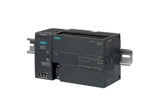
Siemens S7-200 SMART Häufige Fragen zur seriellen Kommunikation
Release-Zeit:2023-07-27 11:39:28
1. Does the S7-200 SMART support Modbus ASCII communication mode?
STEP 7- The Micro/WIN SMART software does not provide the Modbus ASCII communication mode instruction library. If the S7-200 SMART CPU is used for Modbus ASCII communication, it requires the user to use the free port communication mode for programming.
2. Can the RS485 port (port 0) and the SB CM01 signal board (port 1) integrated with the S7-200 SMART CPU function as the Modbus RTU master station or slave station at the same time?
S7-200 SMART V2.2 supports two communication ports as the primary MODBUS RTU station at the same time, but not as the secondary MODBUS RTU station.
3. How does the S7-200 SMART CPU as Modbus RTU master access the hold register whose Modbus address range is greater than 49999?
Generally, the Modbus protocol's hold register range is between 40001 and 49999, which is sufficient for most applications, but some Modbus slave hold register area addresses will be outside this range. The Modbus RTU master protocol library supports holding register address ranges (40001 to 49999) or (400001 to 465536). If the Modbus slave address range is 400001-465536, simply assign the appropriate value to the Addr parameter when invoking the MBUS_MSG subroutine, such as 416768.
4. When the S7-200 SMART CPU, as the Modbus RTU master station, invokes the MBUS_MSG command for many times, why does the command show 6# error code?
1. Only one MBUS_MSG command can be activated at a time. If multiple MBUS_MSG commands are activated, ** MBUS_MSG commands will be executed. All subsequent MBUS_MSG commands will abort execution and 6# error codes will appear. Multiple MBUS_MSG commands need to be executed in polling mode.
2. The proposed address area allocated in the Modbus library storage area overlaps with the V storage area already used in programming.
5. Die S7-200 SMART CPU fungiert als Modbus RTU Master Station. Wenn die Slave Station defekt ist oder die Kommunikationsleitung unterbrochen ist, versucht die Master Station, mehrere Anfragepakete zu senden, was zu einer langen Kommunikationszeit führt. Wie kann man die Anzahl der erneuten Übertragungen der Master Station reduzieren, um die Kommunikationseffizienz zu verbessern?
Wenn der Befehl MBUS _ MSG aktiviert ist, sendet sie den Modbus-Anforderungsnachrichtenrahmen. Wenn die Masterstation die Antwort von der Slave-Station nicht innerhalb des durch den Timeout-Parameter definierten Zeitintervalls erhält, sendet die Modbus RTU-Masterprotokollbibliothek standardmäßig zwei weitere Modbus-Anforderungsnachrichtenrahmen. Das Fertig-Abschlussbit des MBUS _ MSG-Befehls wird erst nach dem Senden des letzten Anforderungsrahmens auf 1 gesetzt und nach dem durch den Timeout-Parameter definierten Intervall wird keine Antwort empfangen. Wenn Sie den Wert der Variable mModbusRetries von 2 auf 0 ändern, können Sie die Wiederholungszeiten von Modbus-Anforderungsrahmen abbrechen. Die * * -Adresse der Variablen mModbusRetries kann durch Abfrage der Symboltabelle der Modbus RTU-Masterprotokollbibliothek ermittelt werden, wie in Abbildung 1 dargestellt.
-
 202212-29
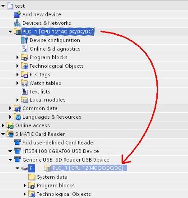
Siemens lädt Gegenstände im Transfermodus auf eine Speicherkarte
Lädt Elemente im Übertragungsmodus auf eine SpeicherkarteSchritt 1: Stellen Sie die Speicherkarte gemäß der obigen Methode auf & quot; Karten & quot; übertragen. Es wird empfohlen, alle Dateien v···
-
 202212-30
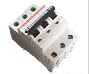
Ausfall und Behandlung von ABB-Unterbrechern
Beurteilung und Behandlung von & quot; Ablehnung & quot; FehlernDas Auftreten von & quot; Ablehnung & quot; Situation, im Wesentlichen in den Schließvorgang und Wiedereinschaltvorgang. Diese Art von ···
-
 202302-15
Wie kalibriert man den Touchscreen?
Wenn das Passwort der Systemeinstellungen der Verantone Touchscreen-Hardware verloren geht, können Sie die Werkseinstellungen durch Systeminitialisierung wiederherstellen. Es gibt vier Möglichkeiten···
-
 202301-09
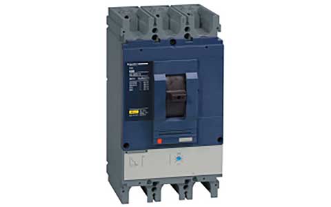
Schneider-Rahmen-Leistungsschalter MT-Leistungsschalter konnte das Schalterproblem nicht schließen
Schneider Strukturschutzschalter hat keine Energie gespeichert (prüfen Sie die Stromversorgung des Energiespeichermotors, falls normal, prüfen Sie, ob die Energie manuell gespeichert werden kann)MX-···
-
 202212-29
Hinweise zum Einsatz von Siemens Frequenzumrichtern
1. Die Ausgangsleitungsseite des Siemens-Frequenzumrichters kann nicht kurzgeschlossen werden, um den Kondensator zu kompensieren, noch kann der Kondensator kurzgeschlossen werden, um die hohen Obersc···


 +86 13811814778
 +86 13811814778
 Gebäude 26, Gemeinde Liyuan, Bezirk Chaoyang, Peking, China