
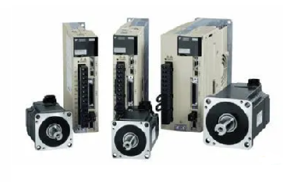
Yaskawa-Servoantrieb-Debugging-Verfahrensschritte
Release-Zeit:2023-09-14 14:57:39
1. Basic wiring
The main power input is 220V, which is connected from L1 and L3 (the actual use should refer to the operation manual); Control power input r, t can also be directly connected - 220V; Motor wiring see page 22, 23 of the operation manual, encoder wiring see the operation manual, do not connect wrong.
Second, test steps
1.JOG test machine function Yaskawa servo can be tested only according to basic wiring; When the digital display is in the initial state 'r 0', press the 'SET' key, then press the 'MODE' key continuously until the digital display is' AF -- AcL ', then press the up and down keys to 'AF-JOG'; Press the 'SET' key to display 'JoG -' : press and hold the '^' key until 'rEAdy' is displayed; Hold down the '<' key until 'SrV-on' is displayed; Press and hold the '^' key to rotate the motor counterclockwise, press the 'V' motor to rotate clockwise, and its speed can be set by the parameter Pr57. Press 'SET' to end.
2. Yaskawa servo internal speed control mode COM+ (7-pin) is connected to +12 -- 24VDC,COM- (41-pin) is connected to the DC source; SRV -- ON (pin 29) connected with COM-; Parameter No.53 and No.05 should be set to 1: (Note that such parameters should be written into EEPROM after modification and re-powered) Adjust parameter No.53 to make the motor rotate. The parameter values are the rotational speed, with positive values for counter-clockwise rotation and negative values for clockwise rotation.
3. Yaskawa servo position control mode
COM+ (7-pin) is connected to +12 -- 24VDC, and COM- (41-pin) is connected to the DC power source; SRV -- ON (pin 29) is connected to COM-LUS1 (pin 3), SIGN1 (pin 5) is connected to the positive terminal of the pulse source (+5V); PLUS2 (pin 4) is connected to pulse signal, SIGN (pin 6) is connected to direction signal; Parameter No.02 is set to 0, No42 to 3, and No43 to 1. PLUS (4 pins) into the pulse signal, can make the motor rotation; Change SIGN2 to change the motor steering. In addition, adjusting parameters No.46 and No.4B can change the number of pulses required per revolution of the motor (that is, electronic gear).
-
 202604-24
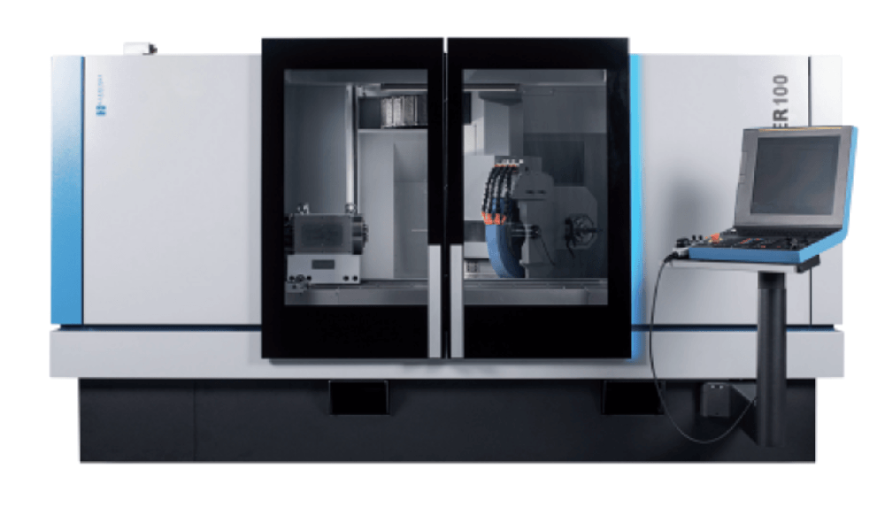
Von Hardinge nach Kellenberger: Eine Marke' Wiedergeburt nach dem Konkurs und ein neuer Start in China
Einmal ein bekannter Name in der weltweiten Werkzeugmaschinenindustrie, hat die in den USA ansässige Hardinge Group Konkursschutz, Vermögensvertrieb und Geschäftsumstrukturierung durchlaufen. Bis D···
-
 202212-29
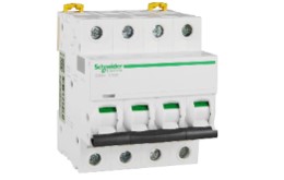
Schneider kleiner Leistungsschalter und Leckageschalter Unterschied
1. Definition des Mini-LeistungsschaltersElektrische Besetzung für kurze MCB, geeignet für die Kommunikation 50 / 60Hz Überspannung 230 / 400V, Überstrom zu 63A Linie Überlast und Kurzschluss War···
-
 202303-03
MCGS touch screen 485 communication precautions
1. Variablen in der Echtzeitlaufzeit können nicht gleichzeitig Kanäle hinzufügen und Funktionen zum Senden von Daten verwenden.2. Im übergeordneten Gerät der universellen seriellen Schnittstelle ···
-
 202302-28
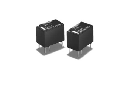
Häufige Fehlerprobleme bei Omron-Relais
I. Überschreiten Sie während der Verwendung des OMRON-Relais nicht den Nennspannungswert des Laststroms, denn wenn die Nennspannung zu hoch ist, kann es zu einem lokalen Kurzschluss zwischen den Spu···
-
 202302-17
959698 Gründe für den Ausfall des Siemens 3RW44 Sanftanlassers
3RW44 Softstarter 95,96,98 ist ein umfassender Fehler, was bewirkt, dass er funktioniert?95.96,98 Gründe für den Ausfall des Siemens 3RW44 Sanftanlassers95, 96, 98 ist der normalerweise offene, norm···


 +86 13811814778
 +86 13811814778
 Gebäude 26, Gemeinde Liyuan, Bezirk Chaoyang, Peking, China