
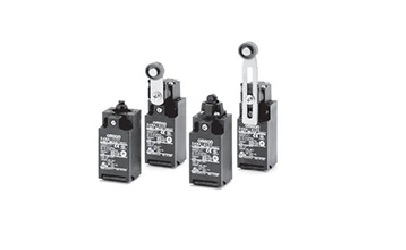
Fehlererkennungsmethoden für Omron-Relais
Release-Zeit:2023-04-21 16:02:21
Fault detection Method One
1. You can first check whether the voltage of the Omron relay is high or low. Generally, the maximum voltage is between 180V and 240V.
Fault detection Method two
2. In addition, when the Omron relay fails, the first thing to check is the external connection of the relay, to see whether the connection of the relay contacts is wrong or broken, falling off or other abnormal phenomena.
Fault detection Method three
3. Next, you can check the power supply circuit of Omron relay and use the meter to test whether the voltage of positive and negative power supplies is the same. If the voltage value measured is the same, it can be inferred that the relay is normal. If the voltage is not a problem, then the power amplifier delay and protection circuit can be carried out.
Fault detection Method four
4. At this time, the Omron relay also needs to measure the power amplifier's final circuit. You can visually check whether there are components burned. Need to be further measured, power amplifier tube emission stage resistance to the ground has DC voltage (normal value is within 0.7V) if there is DC voltage that is generally the power amplifier at the end of the circuit problem, then the treatment method can only replace a power amplifier tube emission stage resistance.
Omron relay note instructions
1. When installing Omron relay, it must not be pushed in too hard, so as not to damage shafting and code plate. The OMRON relay should be gently pushed into the bushing shaft.
2. When using the Omron relay, it is necessary to check whether the plate spring is loose relative to the Omron relay and whether the screw of the relay is loose, so as to avoid some faults and other accidents in the process of operation.
3. Do not randomly connect the terminal between the Omron relay to the wrong, otherwise it is easy to cause the damage of the Omron relay in power-on operation.
-
 202305-12
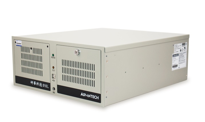
Das Festplattenlicht des Advantech-Industriecomputters 610L leuchtet nicht
Hard disk fault: The hard disk may be faulty, causing the hard disk indicator to be off. You can try to restart the computer. If it still does not light up, check whether the hard disk is recognized b···
-
 202212-29
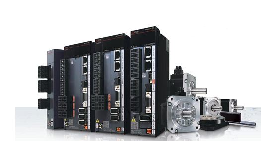
Mitsubishi-Abrufbefehl und Ausgabebefehl
1. LD (Fetch-Befehl) Ein normalerweise offener Kontakt und der linke Busverbindungsbefehl, jede Logikleitung mit normalerweise offenem Kontakt beginnt, diesen Befehl zu verwenden;2. LDI (nehmen Sie di···
-
 202307-20
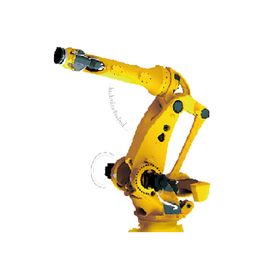
Wie zerlegt man die fünf oder sechs Achsen des Eston-Roboters?
1. Open the shell of the robot to reveal the motor base.2. Use a screwdriver or wrench to remove the screws on the motor base.3. Remove the screw, lift the motor base, and remove it from the robot.4. ···
-
 202512-25
ESTUN Werkzeugmaschine Laden & amp; Entladelösung: Maximierung von Durchsatz, Präzision und Agilität
In der wettbewerbsintensiven Welt der industriellen Bearbeitung bestimmt die Effizienz des Materialhandlings – insbesondere des Be- und Entladens von Werkzeugmaschinen – direkt die Produktionszyklen···
-
 202212-29
Fehleranalyse des WEINVIEW-Touchscreens kann nicht eingeschaltet werden
1. Das Stromkabel ist falsch angeschlossenDies mag offensichtlich erscheinen, aber stellen Sie sicher, dass das Netzkabel an der Rückseite des Touchscreens angeschlossen und an eine Steckdose angesch···


 +86 13811814778
 +86 13811814778
 Gebäude 26, Gemeinde Liyuan, Bezirk Chaoyang, Peking, China